QR Codes
What is a QR Code?
A simple QR code pointing to the aaronjencks.net homepage.
QR Code is short for Quick Response Code, it was designed in 1994 by Denso Wave, for the automotive industry in Japan. A QR code uses four standardized encoding modes (numeric, alphanumeric, byte/binary, and kanji) to store data efficiently. The QR code is widely used today because of its fast read times, and the vast amount of data storage capability that it has compared to a standard barcode.
QR codes also have superior error correction compared standard barcodes, while a simple barcode uses a checksum at the end of its code to validate the data, a QR code uses the Reed-Solomon filter technique. A really fancy way of saying, it uses contextual clues while the scanner is reading the image to guess as to what the correct numbers should be in order to correct error. This technique was also commonly used in CD/DVD readers.
Okay, but what's in it?
QR codes are made up of several regions, refer to the diagram on the right for more information:
- The position indicators specify the region that the code encompasses and represent the three squares in the upper right, left, and lower left corners
- The alignment indicators are used to help with maintaining stability while decoding and are represented by the smaller squares, most commonly found in the bottom right corner, but are actually spaced regularly starting 7 squares from the outer border on each side, and then spaced evenly every 22 pixels in the four cardinal directions.

A diagram of the functional regions of a QR code, Wikipedia
- The timing indicators help the decoder determine what consitutes as a single white space and a single black space, they are represented by dashed lines going along the vertical left side and the horizontal top
- The version information helps the decoder know how large the code is, and how much data should be inside, it does not however specify exactly how much data, or what kind it is, inside of the code, just the overall size of the image.
- The formatting information different from the bitstream formatting information, is used to tell the decoder the level of error correction detail and the default mask pattern, this information is crucial to the decoder, so it is represented using both normal data, BCH code, and is stored with two complete copies in every code. The formatting information is wrapped around the upper left corner's position indicator, is on the bottom of the upper right position indicator and on the right side of the lower left position indicator.
- And last but not least, the data represents the bulk of the data in the image, and is represented using an interesting interpretation of a bit stream.
Formatting information
The formatting area of a QR code contains 4 areas, the error correction level, the mask pattern code, and the BCH code used for error correction. See the picture on the right for what the different combinations are for the error correction level bits, and the mask pattern bits are.
Mask Patterns
Mask patterns are pretty simple, these fill up the blank space after the data gets encoded, if any, each one uses on of the algorithms show in the figure on the right, it is determined by the 3 formatting bits also shown in the figure to the right.
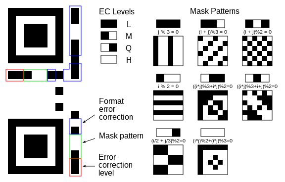
A diagram of the formatting regions and mask patterns of a QR code, Wikipedia
The calculated information
The last 10 bits in the formatting area are actually calculated, they are created using something called a
. In this post I'm only going to talk about encoding, or generation of, a BCH code and not decoding. To create a BCH code you need to take some sort of 'seed' polynomial and pass it through a Generator Polynomial using a special form of polynomial division unique to
. Now, normally you would need to create a generator polynomial and use something called a
, but luckily, some really nice guy on Wikipedia gave out all of the information needed to make QR code polynomials. So all we have to do, it use the information from the Error correction level, and the mask pattern as coefficients for some 'seed' polynomial, multiply it by X^10, and then use polynomial division (described below) to find the resulting BCH polynomials, the last 10 pixels in the formatting data correspond to coefficients of this polynomial. When I build my implementation, there was an assumption that I had to make here that I can't back up with fact, but: The first bit of the error correction level represents X^5 and all following bits represent the corresponding decreasing power. and Bit 9 represents the highest power of the output polynomial and each bit after decreases in power just like the previous statement .
This is an example of how to do the generator polynomial division for the formatting bits where:
Divisor is the generator polynomial
The input is 'seed' value created from the error correction level bits, and the mask pattern bits.
It's padded with 10 bits, not 3.
11010011101100 000 <--- input right padded by 3 bits

1011               <--- divisor

01100011101100 000 <--- result (note the first four bits are the XOR with the divisor beneath, the rest of the bits are unchanged)

 1011              <--- divisor ...

00111011101100 000

  1011

00010111101100 000

   1011

00000001101100 000 <--- note that the divisor moves over to align with the next 1 in the dividend (since quotient for that step was zero)

       1011             (in other words, it doesn't necessarily move one bit per iteration)

00000000110100 000

        1011

00000000011000 000

         1011

00000000001110 000

          1011

00000000000101 000

           101 1

-----------------

00000000000000 100 <--- remainder (3 bits).  Division algorithm stops here as dividend is equal to zero.
So, when it comes to actually doing the calculation, the generator polynomial for QR codes is constant as: X^10 + X^8 + X^5 + X^4 + X^2 + X + 1
A better example than Wikipedia supplies:
Lets say you choose low error correction level ([1, 1]) , and mask pattern 5 (((i * j) % 3 + i * j) % 2 = 0) ([0, 1, 1])

So the 'seed' polynomial is:
(X^5 + X^4 + X^2 + X) * X^10 = X^15 + X^14 + X^12 + X^11

so, the division looks like:

1101100000000000 : 0000000000

10100110111

0111111011100000 : 0000000000

 10100110111

0010110110010000 : 0000000000

  10100110111

0000010000101000 : 0000000000

     10100110111

0000000100011111 : 0000000000

       101001101   11

0000000001010010 : 1100000000

         1010011   0111

0000000000000001 : 1011000000

               1   0100110111

0000000000000000 : 1111110111 <-- Result

-----------------------------

Thus the bits 9-0 of the formatting code is 1111110111

A diagram of the formatting regions and mask patterns layout of a QR code, Wikipedia
Data Layout
The data layout of a QR Code is quite interesting, but on a fundamental level, it just kind of makes sense. The data in a QR code is encoded starting from the lower right side, heading upwards, it is then snaked around alternating up and down until all of the data is encoded. Then the rest of space is filled in using the mask pattern.
An interesting thing about the data is that, it goes in reverse order from what you think, meaning that for each byte that's encoded, the encoding starts at bit 7 and then works its way down to 0, in an alternating zig-zag starting on the right, going to the left, moving up a row, back to the right, then the left, etc... In the case that there is an obstacle, the bit that would be placed next is placed in the next available spot, basically, keep going from where you left off (see figure to the right).
The diagram on the right is also an excellent example of the data stream layout and direction of data encoding.
Data Stream Encoding
Lets talk about how we put the data into the correct format to be read by the QR code. The format of data in a QR code follows the general pattern:
[ Mode Indicator][ Mode bitstream ] --> [ Mode Indicator][ Mode bitstream ] --> etc... --> [ 0000 End of message (Terminator) ]
| Mode Indicator | Description | Typical Structure |
|---|---|---|
| 0001 | Numeric | [0001 : 4] [ Character Count Indicator : variable ] [ Data Bit Stream : 10 × charcount ] |
| 0010 | Alphanumeric | [0010 : 4] [ Character Count Indicator : variable ] [ Data Bit Stream : 11 × charcount ] |
| 0100 | Byte Encoding | [0100 : 4] [ Character Count Indicator : variable ] [ Data Bit Stream : 8 × charcount ] |
| 1000 | Kanji Encoding | [1000 : 4] [ Character Count Indicator : variable ] [ Data Bit Stream : 13 × charcount ] |
| 0011 | Structured Append | [0011 : 4] [ Symbol Position : 4 ] [ Total Symbols: 4 ] [ Parity : 8 ] |
| 0111 | ECI | [0111 : 4] [ ECI Assignment number : variable ] |
| 0101 | FNC1 in first position | [0101 : 4] [ Numeric/Alphanumeric/Byte/Kanji payload : variable ] |
| 1001 | FNC1 in second position | [1001 : 4] [ Application Indicator : 8 ] [ Numeric/Alphanumeric/Byte/Kanji payload : variable ] |
| 0000 | End of message | [0000 : 4] |
Table courtesy of Wikipedia
As you can probably tell, this generic setup allows for the compounding of different types of data for really efficient storage, but it also means that QR codes have a limitless data encoding amount, despite what the standard tells you, but do be aware if you go beyond the standard limit of about 3k characters, don't expect a standard QR code decoder to be able to decode your image.
Fore more information on how many bits go into each encoding type or how to encode the alphanumeric data, visit the QR code wikipedia article.
And now, for the main point of this post, here is the first million digits of pi encoded into a QR code:
My coding project
As you can probably guess I also implemented this code, hence how I have the above picture, and you can explore it Here!


Comments
Post a Comment